-40%
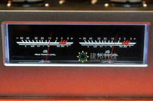
VU meter head / level meter / DB audio power meter + Driver board
$ 22.17
- Description
- Size Guide
Description
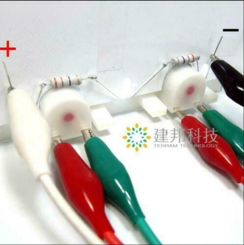
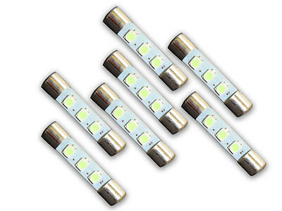
Lamp Specifications: White Backlight LED 2.8-3.6V 20mA ( we will connect 2 Resistors on the VU header to change the backlight voltage to 12V)Signal input
: The driver board provides two kinds of signal input methods, which can be arbitrarily selected according to your situation!
(Hint: If the signal is taken at the back end of the volume potentiometer or the output of the amplifier, the pointer swing will be controlled by the volume potentiometer, that is, the volume of the large pointer swings large, and the volume is small, the pointer swing is small.)
1 LOW, GND, LOW: This is the low-level signal input terminal of the driver board. It is used to connect the audio signals of the CD player, computer sound card, preamp, and other audio source devices. When wiring, LOW, GND, and LOW correspond respectively: Left,
The ground and right channel can be used.
(Adjust the two potentiometers on the driver board to control the size of the hand swing. If the signal is full, the pointer swing fails to reach your desired value, or the volume becomes small, you can press R2 on the driver board.
The R3 resistor is removed. R2 and R3 are the grounding attenuation resistors used when the driver board is connected to the high-level input signal. It is only used when the high-level input is used.
2:HIGH, GND, HIGH: This is the high-level signal input terminal of the driver board. It is used to connect the amplified power signal through the power amplifier. The attenuation circuit in the driver board will attenuate the high-intensity level of the amplifier output.
The driver IC, the attenuation circuit contains the resistors R2 and R3 just mentioned. When connecting the output terminals of the power amplifier, the two HIGH terminals of the driver board are respectively connected to the two red terminals of the power amplifier, and the two black terminals of the power amplifier.
Select one of the GND terminals of the driver board.
Drive output:
V+, V-, terminal: This is the two sets of 12V backlight power supply output terminals provided by the driver board for the backlight of the meter. Please pay attention to the voltage and positive and negative direction of the head light source when connecting.
+, -, terminal: This is the output terminal of the drive board drive meter, which is connected to the "+" and "-" terminals of the two level meters. Pay attention to the positive and negative directions when connecting.
3. Driver board Power supply parameters:
Works
voltage: AC or DC 12-15V (recommended to use a separate power transformer, or independent winding power supply!)
Rated power: 3W
4. Driver board PCB size: 60*39mm
Package include: VU header X 1
Driver board X 1
connect cable X 0.5M
we have the suitable case:
https://www.ebay.com/itm/163901550415
